Multicast
OVERVIEW
The vast majority of communication in traditional IT networks runs as unicast, meaning that messages are always sent from a single source to a single destination. While this method is perfectly sufficient to transport video and audio signals between two devices it would mean doubling the amount of data being sent if one source were to send the same video to two destinations; so, this method does not scale if applied to a traditional broadcast infrastructure where a router is able to distribute a single source to as many outputs as the router is equipped with.
To alleviate this limitation, data transmission with a multicast addressing scheme is used, which allows sending data to a group of destinations without the need for the source to send the data multiple times. The actual distribution of data to the destinations is handled by the network elements (switches and routers) connecting the source with the destinations: the source sends the data once and the switch will duplicate the packet for each destination.
If the switch does not know which destination is interested in which source, it needs to duplicate the source packets on every port, thereby turning the multicast into a broadcast. This is very inefficient in terms of bandwidth usage and does not scale well.
To orchestrate multicast in a more efficient way, the Internet Group Management Protocol (IGMP) is used. A destination interested in a certain stream will send a “Join” message. Switches can listen to IGMP communication (“IGMP snooping”) and use this information to selectively duplicate the data stream to the port on which the destination is attached. The destination becomes a “member” in the requested “multicast group”. The switch keeps track of all members of a multicast group and sends periodic queries (“membership queries”) whether they are still interested – the switch acts as an “IGMP Querier”. If a destination does not reply in a specified time, the switch assumes that the destination is no longer interested and stops duplicating the packets. In more recent versions of IGMP, the destinations can also send “leave” messages, actively informing the switch about not wanting the multicast data anymore (see below).
IGMP Snooping and IGMP Querier are features not found on all switches but are needed for a correct and performant network function in the realm of audio / video networking. The V__line switch has both of these features built-in.
When referring to multicast people usually talk about the layer 2 Ethernet multicast, limiting the data distribution to a single subnet. In larger setups, when the layer 2 domains get too large, a separation into several smaller networks might be desirable. Every network, usually kept in its own VLAN, needs its own IGMP Querier and IGMP snooping to be enabled. To transfer data between the different subnets, IP routing is necessary. This is done by a dedicated router or a routing-enabled switch. In case of media data using multicast, a more specialized form of routing is necessary: PIM. This feature can only be found in carrier-grade / enterprise-grade switches or dedicated routers.
In setups where a more rigid and deterministic control is necessary, other means of routing multicast data might be necessary to ensure correct audio and video distribution, such as an application layer-based control of the audio and video streams (sometimes termed an “Software Defined Network” or “SDN”).
Multicast uses a reserved range of IP addresses to identify a multicast group (224.0.0.0 to 239.255.255.255 for IPv4). Some of them are reserved for specific protocols or purposes (e.g. 224.0.0.1 for all systems on this subnet or 224.0.0.22 for IGMP messages). The range of 239.0.0.0 to 239.255.255.255 can be freely used.
QUERIER ELECTION
There will be only one querier (one device managing multicast group information) per subnet / VLAN. This querier is elected between all the devices capable of fulfilling this task.
When such a device starts, it multicasts a general query to all other systems to the 224.0.0.1 address using its own (unicast) IP address as source address. When a device receives such a query it compares the source IP from the message with its own IP address. The device with the lowest IP address is elected to be the querier for the subnet.
All other devices start an internal timer which is reset every time they receive a general query from the querier. If those messages cease, a new querier election takes place after the timer expires.
In larger installations the querier role is usually taken by a multicast capable router, which handles the data exchange to and from other subnets.
MULTICAST ROUTER PORT
Network elements need to differentiate between ports to which hosts are attached and ports to which other multicast-aware network elements are attached. Ports to which hosts are connected receive only those multicasts which they have explicitly requested using IGMP “join” messages. Ports to which routers are connected commonly receive all multicasts, so that they can forward the multicast traffic to other network segments.
Switches receiving general IGMP queries on a specific port assume by default, that this port is connected to a multicast router that is interested in all multicast traffic. This port is generally termed a multicast router (“mrouter”) port. Since the switch has no knowledge about the group membership of hosts in other subnets, it simply sends all the local multicast traffic to all mrouter ports (also referred to as “multicast data flooding”). In media applications, especially with high-bandwidth video streaming, this behavior might be undesirable, since it can easily lead to congestion on the mrouter ports.
Since the V__line contains its own switch, many switches will recognize the V__line as a multicast router and flood all multicast traffic to the V__line.
To counteract this behavior three options exist:
- disabling the mrouter port learning on the switch
- disabling the multicast data flooding on the switch (aka “report flooding”, see below)
- disabling the V__line’s IGMP querier function
Disabling the mrouter port learning alleviates the issue above, but also necessitates that you manually need to assign mrouter ports where you want the multicast traffic to be forwarded without explicit IGMP “join” messages.
Disabling the V__line’s IGMP querier function leads to the V__line no longer sending general IGMP queries and thus not being recognized as a multicast router anymore. This can be done without negative side-effects, provided the network has another active IGMP querier (e.g. the switch).
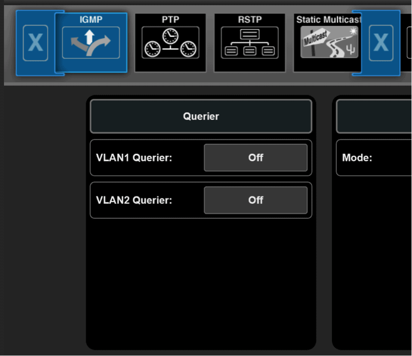
For switches that support report flooding, we recommend using this functionality. For other switches we recommend disabling the V__line’s IGMP querier function (“Settings” –> “Switch” –> “IGMP”):
IGMP REPORT FLOODING
To overcome the restrictions that might occur from multicast router port learning and the multicast data flooding, an alternative port mode for inter-switch links is available on some switches: IGMP report flooding.
If a port is in this mode, automatic multicast router port learning is disabled, and multicast data flooding is inhibited as well. A port will be included in a multicast group only, when IGMP snooping has detected an IGMP membership report for it. Whenever a locally attached node sends an IGMP membership report, it is reflected to all ports in IGMP Report Flooding Mode. This allows the neighboring network device to correctly detect memberships across switches without flooding multicast data unnecessarily.
This mode leads to slightly higher IGMP traffic and IGMP snooping workload in a layer 2 domain, but effectively avoids congestion on inter-switch links.
IGMP Report Flooding Mode is the preferred mode in a medium sized, flat hierarchy layer 2 topology. The V__line built-in switch supports IGMP Report Flooding as well.
UNREGISTERED MULTICAST FLOODING
The default behavior of most switches with multicast traffic not being registered by IGMP join or membership reports, is to deliver the traffic to all ports, thus turning it into a broadcast. This is not acceptable when predictive and well-controlled bandwidth allocation is needed. Media applications must be capable of properly speaking IGMP to achieve stable multicast network operation.
Use the switch configuration to turn off unregistered multicast flooding (this feature is also referred to as “Unregistered Multicast Filtering”).
IGMP FAST LEAVE
IGMP Fast Leave was introduced with version 2 of IGMP. It refers to the capability of a host to explicitly announce that it is no longer interested in a specific multicast. The host sends out an IGMP “leave” message and the network immediately stops the delivery of multicast traffic. In version 1 of IGMP there was no leave message and a timeout was required to determine that a host no longer wanted to consume a specific multicast.
The advantage of fast leave is that the multicast traffic ceases immediately and does not consume any more network resources. It allows quickly re-using the bandwidth for another stream.
Since the implementations of the fast leave feature are different across device vendors, our recommendation is to verify correct functionality of fast leave in a concrete system setup before using it in production. Alternatively disable fast leave in the complete system (sources, switches and destinations).
For the V__line the respective settings can be found in “Settings” –> “Switch” –> “IGMP”:

FAST LEAVE TESTED SCENARIOS
| Scenario | Result |
| V__lines (SW 1.4.0.106) connected to Arista 7150 (SW 4.20.3), Layer2, Immediate Leave activated on all devices | OK |
MULTICAST ADDRESS CONSIDERATION
In the early days of the internet the address block 224.0.0.0/4 was reserved for multicast and designated “class D”.
This range has been split into multiple smaller ranges as outlined in RFC 5771, e.g. the range of 224.0.0.0 to 224.0.0.255 was reserved for use in local subnets and is used today in routing protocols such as OSPF.
The range of 239.0.0.0/8 has been reserved for private use within an organization (RFC 2365) and is commonly used and recommended for A/V streaming.
One additional thing to be aware of:
In the layer 2 domain, every multicast address is translated into a destination MAC address. As of design, the first half of the MAC address for multicast IP addresses is fixed to 01:00:5E (by OUI / IEEE; RFC 1112). The other half of the MAC address (the remaining 3 octets or 24 bits), will be derived from the last 24 bits of the multicast IP address.
Of these last 24 bits, the least significant bit of the first octet is always set to “1”, leaving only 23 bits which are then taken from the IPv4 multicast address (RFC 7042). This causes different multicast addresses to be translated into the same MAC address: “1000 0000” and “0000 0000” for the octet are the same; resulting in e.g. 228.0.1.1 and 233.128.1.1 being translated into the same MAC address.
This behavior needs to be considered when creating a multicast address schema in order to avoid collisions.
IGMP PERFORMANCE
The performance needed depends on the system size and expectations of the users. Usually switches process IGMP requests serially, so if 100 Joins messages need to be processed and each Join request takes 10ms, the 100 requests take a total of 1 second.
Looking at the emerging standards such as VSF TR-03 / SMPTE ST-2110 the goal is to separate the essence streams into video, audio and metadata. Assuming each audio stream carries 4 channels, the representation of each SDI signal results in 1 video stream, 4 audio streams (4x 4ch) and 1 metadata stream (VANC data, such as captions), a total of 6 streams in need to separate handling with IGMP.
Equating this to a normal baseband router of 500×500 signals, assuming that 25% of the signals need to be switched simultaneously at peak times and that the users’ expectation is that the switching signals takes 5 frames at maximum, this results in:
- 125 signals to be switched (25% of 500 signals)
- 750 resulting streams (6 streams per signal * 125 signals)
- Total time available for switching: 100ms (assuming 50fps)
- Many of the signals switched will require a “Leave” and a “Join” command, effectively doubling the number to 1500 requests for 750 streams
With 1500 requests to be processed in 100ms that leaves 67µs per request, if the requests are in fact processed sequentially.
The total time needed to establish a new essence connection needs to also take into account how much time the source and the destination devices need to create, provide and consume the new stream.
Looking at those numbers and being aware that the latency of IGMP message processing increases when using a network with multiple cascaded switches, it becomes apparent that solely using IGMP to control the essence flows inside a media network will only be practical for limited size networks. Other control mechanisms will be needed to allow building bigger systems.
“HALF IGMP” MODE
As outlined above the total time taken to establish a new multicast data stream is composed of the time it takes for the IGMP message processing, the time for the source to setup the new multicast stream and the time for the destination to consume the stream.
Some source devices, such as the Lawo V__line, allow to “force” sending the multicast data to the switch, despite no one having requested the specific multicast data yet. This reduces the amount of time to establish the multicast data stream, since the source is already sending.
This behavior has no adverse side effects, provided the switch is configured correctly, as the switch will discard the incoming multicast data stream until a destination actually requests it.
To activate half IGMP mode and force the sending of streams irrespective of IGMP “join” messages, set the Stream Mode to the respective interface(s) in “Settings” –> “TX Stream” –> “RAW SDP” (or “J2K SDP”, “Ravenna SDP”, et. al.):
This can be done on a stream-by-stream basis.

PROTOCOL INDEPENDENT MULTICAST (PIM)
PIM is used to route multicast traffic across layer 3. It does not use its own routing tables but relies on information provided by routing protocols. That means that routing needs to be established, e.g. via OSPF or BGP protocols, in order for PIM to work.
There are four variants of PIM:
- Sparse Mode
- Dense Mode
- Bidirectional PIM
- PIM Source-Specific Multicast
Sparse Mode is the most commonly used mode in broadcast currently.
PIM Sparse Mode
PIM uses the concept of a Rendezvous Point (RP) to collect information about available multicasts in the network. This Rendezvous Point is a service running on one or multiple routers in the network. It will be informed about any multicasts present in the network and will be asked for the location of a multicast if someone wants to receive it:
As soon as a source host provides a multicast, the router to which the host is connected will inform the RP about this multicast using a PIM Register message. A destination host that is interested in the multicast, sends an IGMP Join message. The router to which the destination host is connected, sends a PIM Join message to the RP. The RP will start forwarding the multicast traffic to the destination host via the destination router – that data flows through the RP (the path in the network is referred to as “Root Path Tree” or “shared distribution tree”). If the routing path through the RP is not the optimal path for the underlying network, the destination router, having learned the source address of the multicast, creates the best route and subsequently start receiving the multicast via the new route (the new path through the network is referred to as “Source Path Tree”).
The changing of paths might lead to interruptions in the data flow and should be avoided by network design and configuration.
In a spine/leaf topology the RP is usually placed as an anycast RP on all spine switches to provide redundancy.